Compare dual-seal buffer and barrier systems through pressure relationships, leakage direction, fluid compatibility, cooling, and operating responsibilities.
On this page
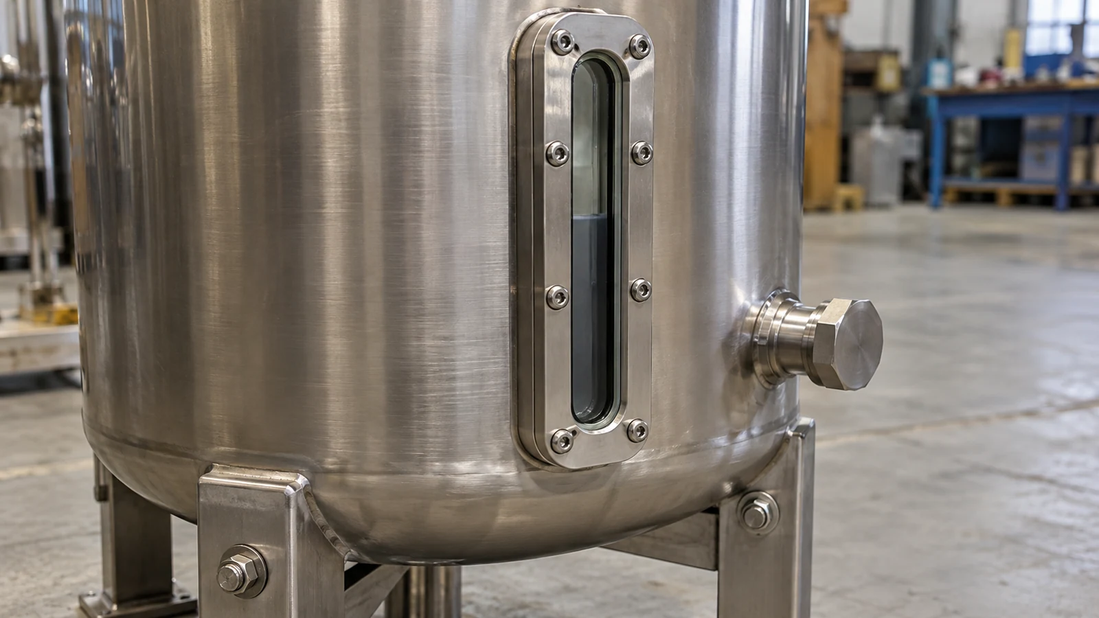
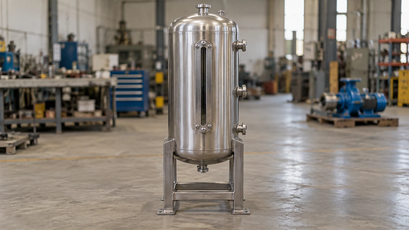
Two dual-seal systems can look similar from the outside: a reservoir, connecting pipework, instruments, and a cooling provision. Their operating purpose can still be very different. Plan 52 uses an unpressurized buffer arrangement; Plan 53A uses a pressurized barrier arrangement.
For the buyer, the decisive issue is the pressure relationship across the inboard seal. It governs the normal direction of leakage and connects product quality, emissions handling, and support-system operation in one decision.
How do buffer and barrier systems differ?
A buffer system operates below seal-chamber pressure, so process leakage across the inboard seal can enter the buffer circuit. A barrier system operates above seal-chamber pressure, so the pressure gradient favors barrier liquid entering the process. The seal arrangement must be designed for the selected pressure relationship.
AESSEAL’s Plan 52 description identifies a depressurized buffer circuit for a dual seal. Its Plan 53A description describes a pressurized barrier circuit and highlights both pressure maintenance and compatibility of barrier fluid with the product.
| Decision | Plan 52 | Plan 53A |
|---|---|---|
| Normal pressure relationship | Buffer below process-side chamber pressure | Barrier above process-side chamber pressure |
| Inboard leakage tendency | Process toward buffer circuit | Barrier toward process |
| Product-quality concern | Process contamination of the buffer | Barrier-liquid addition to the product |
| External connection to define | Vent handling and backpressure | Gas supply and pressure control |
| Operating indicators | Level, pressure, temperature, and leakage behavior | Level, pressure differential, temperature, and consumption |
“Unpressurized” does not necessarily mean exactly atmospheric pressure. The vent destination and its backpressure affect the buffer circuit. The actual pressure at the seal remains the useful value.
Product quality and leakage handling belong in the same decision
Plan 52 can be useful where adding barrier liquid to the process is undesirable and leakage into the buffer system can be managed. The buffer circuit then becomes part of the leakage-handling arrangement. Volatile process leakage, liquid accumulation, and vent-system behavior need to be considered together.
In Plan 53A, the selected barrier liquid becomes a potential process contaminant. Compatibility includes the process reaction, downstream separation, final product specification, and the amount of addition the process can accept. A chemically stable fluid can still be unsuitable for a high-purity product.
The choice is consequently more specific than assigning one plan to “safe” fluids and another to “hazardous” fluids. The project needs an acceptable leakage route, a suitable seal arrangement, and operating provisions for the actual consequences of losing that route. Site environmental and process requirements determine what is acceptable.
This relationship should be visible on the P&ID. A vent connection shown without its destination or backpressure leaves part of Plan 52 undefined. A gas connection shown without a usable supply range and pressure-control basis leaves part of Plan 53A undefined.
Pressure control has to follow the process states
The required hierarchy must exist when the seal needs it, including startup, normal running, shutdown, and standby. A fixed barrier setting based only on normal operation may be inadequate if chamber pressure rises during another state.
For Plan 53A, compare the lowest available barrier pressure at the seal with the highest relevant chamber pressure, allowing for the selected design’s required differential. Use the same gauge or absolute reference for both values. The seal manufacturer’s limits and the project specification determine the actual operating margin.
A compact state table is more informative than one pressure value:
| State | Question the pressure schedule must answer |
|---|---|
| Before rotation | Is the required fluid level and pressure relationship established? |
| Normal running | Is the differential maintained throughout the duty range? |
| Process transient | How do chamber and support pressures change relative to each other? |
| Shutdown | Is pressure or heat trapped after the shaft stops? |
| Supply loss | Which alarm or operating action responds before the arrangement leaves its intended condition? |
If barrier pressure is lost, the normal leakage direction can change. The operating response should be defined for the installed seal and process; a pressure loss is not a routine conversion of the system into another approved piping plan.
Cooling depends on circulation as well as reservoir size
The circulating liquid carries heat away from the faces. Reservoir volume provides inventory, but it does not by itself establish adequate heat removal. Pumping features in the seal, pipe resistance, elevation, cooling arrangement, and fluid viscosity all affect performance.
The system therefore needs a thermal duty and a circulation basis. A larger vessel may increase the time before the fluid heats up while doing little to improve the steady heat balance. At low shaft speed or during a hot standstill, the means of moving and cooling the fluid can differ from normal running.
Plan 53A also places pressurizing gas in contact with the barrier liquid. Gas dissolution and release can matter for some fluid and pressure combinations. That is one reason to compare the pressure-support approach for the duty rather than selecting 53A, 53B, or 53C solely by the apparent simplicity of the hardware.
Turn the choice into a comparable package
After selecting the pressure arrangement, the seal support-system RFQ can define the full supply boundary. The comparison should preserve the selected seal configuration, fluid specification, pressure envelope, heat duty, instruments, cooling utility, and refill method.
For Plan 52, the package needs a clear account of where accumulated liquid and vented vapor go. For Plan 53A, it needs a clear account of how pressure is maintained and how barrier consumption is replenished. Both need an operating response to abnormal level, pressure, or temperature.
The purchase is complete when the reservoir, seal, and plant interfaces describe one operating system. The visible similarity of two vessels then stops being misleading: the pressure hierarchy and fluid destination explain why one arrangement fits the process better.
Put the guide into practice
Related specification and RFQ pages
Frequently asked questions
Does Plan 53A mean a system will consume no barrier fluid?+
No. A pressurized barrier arrangement allows a small flow of barrier liquid across the faces, including toward the process. Expected consumption, refill practice, and the response to an abnormal level trend belong in the system design.
Are Plan 53A, 53B, and 53C interchangeable reservoir options?+
They use different methods of maintaining barrier pressure. Their pressure response, gas contact, sizing, and operating requirements differ, so the selected subtype must be evaluated with the seal and the process pressure range.
Continue researching