Calculate annual seal-flush volume and cost, distinguish injected water from cooling-water circulation, and compare improvements without starving the seal faces.
On this page
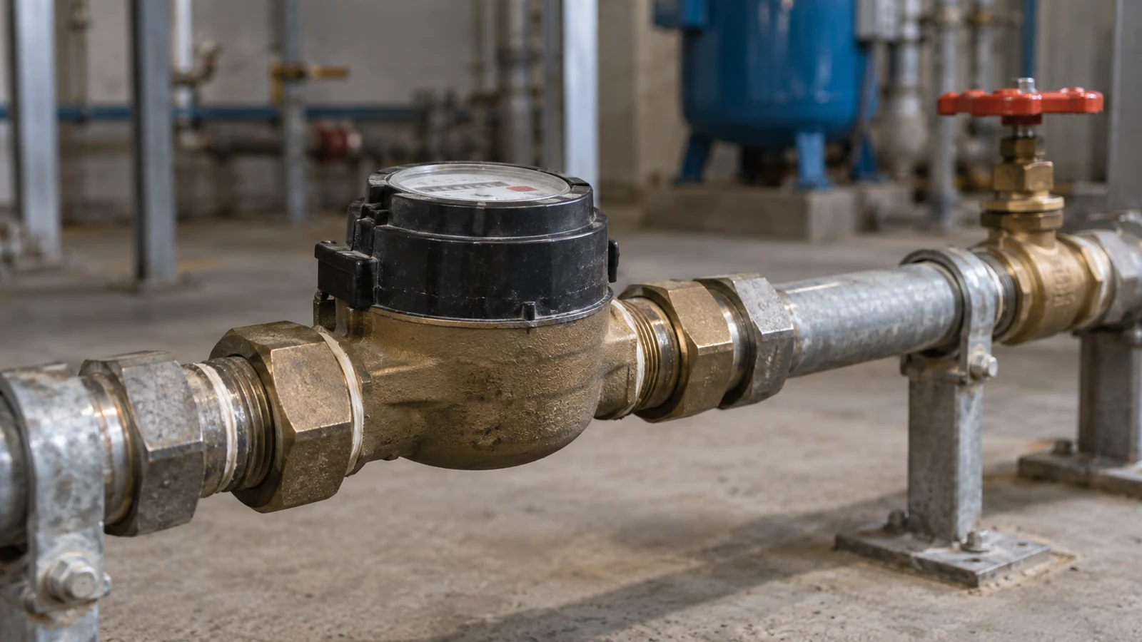
A seal-water meter reading of 2 L/min looks small beside the main process flow. Left open for 8,000 hours, it delivers 960 m³ in a year. Across a fleet, that can become a meaningful utility load and, where the flush enters the product, a process cost as well.
Reducing that cost starts with identifying where the water goes. Water injected into a pump chamber, liquid circulating around a seal, and water passing through the utility side of a cooler serve different purposes. They need separate measurements and separate cost boundaries.
How do you calculate annual seal-flush water use?
Multiply measured flow in litres per minute by the actual hours that the supply remains open, then convert litres to cubic metres. Include standby or shutdown periods if the flush continues during those states.
Annual volume (m³) = flow (L/min) × 60 × open hours ÷ 1,000
For 2 L/min and 8,000 hours:
2 × 60 × 8,000 ÷ 1,000 = 960 m³/year
If a combined supply-and-treatment charge is assumed to be $3/m³, the corresponding direct annual charge is $2,880 per seal. Ten identical duties would total 9,600 m³ and $28,800. These are transparent example assumptions, not a typical plant tariff or a promised saving.
Use measured flow where possible. A valve position does not uniquely determine flow when header pressure, chamber pressure, or line resistance changes. A spot measurement at full production also misses consumption during idle periods. A short survey that covers the principal operating states gives a better annual estimate.
The water bill may cover only part of the cost
An external flush can add liquid to the process. AESSEAL’s Plan 32 guidance specifically identifies fluid compatibility, process contamination, and the expense of the external supply as selection considerations.
The added liquid may need to be heated, cooled, separated, evaporated, or treated downstream. Which costs apply depends on its actual route through the plant.
| Cost element | Calculation input | Boundary to keep clear |
|---|---|---|
| Water supply or preparation | Metered volume and marginal unit cost | Avoid adding a treatment charge already included in the tariff |
| Heating or cooling | Mass flow, heat capacity, temperature change | Include only additional energy caused by the flush |
| Effluent treatment | Additional discharge and treatment demand | Not all injected water necessarily reaches the same effluent stream |
| Product dilution | Added mass or volume relative to process throughput | Use the relevant product concentration and quality limit |
| Equipment maintenance | Meter, filter, valve, cooler, and seal work | Separate routine cost from a claimed reliability improvement |
For example, heating the illustrative 960 m³ of water through 30 K requires approximately 33,440 kWh of thermal energy, using density of 1,000 kg/m³ and heat capacity of 4.18 kJ/(kg·K). The calculation is 960 × 1,000 × 4.18 × 30 ÷ 3,600. Purchased fuel or electrical input depends on the heating system’s efficiency and any recovered heat.
If the process already needs that water at that temperature, the full heating load is not necessarily an avoidable penalty. The comparison has to follow the actual mass and energy balance.
Lower flow changes the seal’s heat balance
A flush can carry away heat, maintain a suitable liquid environment, and help manage solids or vapor formation. Reducing flow changes those functions as well as the water total.
A simplified heat balance illustrates the tradeoff. Suppose a water stream must carry away 1.5 kW, with density of 1 kg/L and heat capacity of 4.18 kJ/(kg·K). At 2 L/min, its calculated temperature rise is about 10.8 K. At 1 L/min, the rise doubles to about 21.5 K. This example ignores other heat-transfer paths and process mixing; it shows why halving the meter reading is not automatically a suitable operating change.
The actual flow requirement follows the seal and chamber design, heat input, process conditions, and required operating margins. Improvement begins with excess flow above that requirement, losses elsewhere in the utility arrangement, or a more suitable support design.
Where does Plan 23 fit in a water-reduction study?
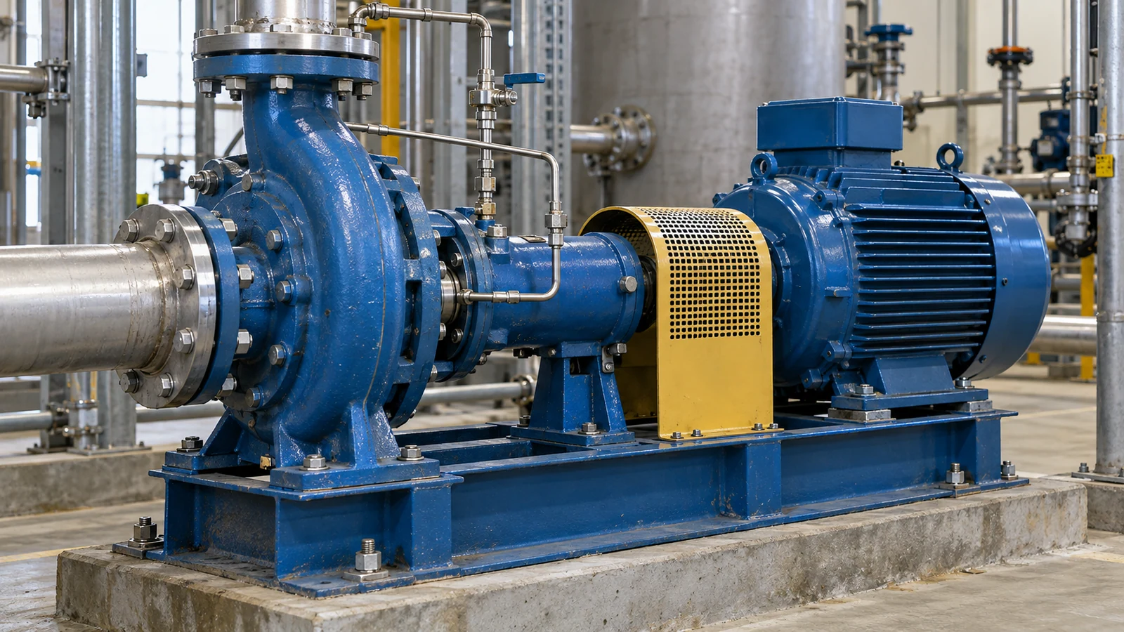
Plan 23 recirculates process liquid from the seal chamber through a heat exchanger and back. For suitable hot, clean duties, that local cooling arrangement can change the need for external flush injection. It still has a cooling duty and requires an appropriate chamber and circulation layout.
AESSEAL’s Plan 23 description identifies a pumping ring during operation and thermosiphon heat transfer at standstill, with installation requirements affecting circulation. The cooler’s process side and utility side are distinct circuits.
A conversion study should therefore compare three quantities separately: external liquid added to the process, liquid circulating in the seal loop, and cooling-water makeup or withdrawal. Calling the arrangement a closed loop does not make all three quantities zero.
For dirty duties, the reason for the original external flush may remain decisive. The Plan 11 and Plan 32 comparison helps separate fluid cleanliness from the desire to reduce utility use.
Build a practical improvement case
Begin with the pumps that combine long running hours, substantial measured flow, and a clear downstream dilution or treatment cost. Record the existing seal and support arrangement so that apparent savings can be tied to a feasible change.
The comparison needs an installed project cost, annual operating cost for each option, and the assumptions behind both. Include new meters, pipework, cooling demand, commissioning, and recurring maintenance where they change. If reliability benefits are expected but not established, keep them separate from the measured water and energy calculation.
After an authorized change, compare flow and operating conditions over equivalent production periods. A lower water reading is useful when the seal remains adequately supported and the process benefit appears at the same boundary used in the proposal. That produces a savings case the plant can track, rather than a percentage reduction detached from how the pump operates.
Put the guide into practice
Related specification and RFQ pages
Frequently asked questions
Does water circulating through a cooler count as water consumed?+
Circulation flow, water withdrawal, and consumptive use are different quantities. A closed cooling-water circuit can circulate a large flow while taking in only makeup water. Meter and report each quantity at the relevant system boundary.
Should the same flush flow be set for every pump in a fleet?+
Use the flow required for each seal, chamber, liquid, and operating range. A fleet survey can find unnecessary variation, but a common setting needs a technical basis for the equipment grouped under it.