Specify obsolete pump replacements using mating-part measurements, material identification, recovered dimensions, and first-part acceptance checks.
On this page
A worn pump shaft can be measured accurately and still produce an inaccurate replacement specification. The measurement may faithfully record a reduced bearing seat, a damaged shoulder, or a groove worn into a seal location. Reproducing those dimensions would reproduce the condition that prompted the replacement.
Reverse engineering therefore combines measurement with reconstruction of the component’s function. The deliverable is a controlled replacement design, with the assumptions about original geometry resolved or clearly assigned for verification.
What should reverse engineering recover?
It should recover the geometry, material condition, interfaces, and performance requirements needed for the replacement to work in the existing assembly. Surface measurements are inputs to that process; they do not all become manufacturing dimensions unchanged.
Sulzer’s pump reverse-engineering description combines scanning and CAD work with engineering assessment and testing. That distinction is useful for a buyer: a digital model, a manufacturing drawing, and an accepted functional replacement are three different deliverables.
Begin by defining the intended result. An exact functional replacement, an alternative manufacturing route, and an upgraded hydraulic component have different engineering scopes. A supplier can quote them more clearly when the options are separated.
Use the mating parts to interpret the sample
The surrounding assembly often contains the information missing from a worn component. A bearing bore, sleeve, coupling hub, housing shoulder, or undamaged spare can help establish the intended fit and axial location.
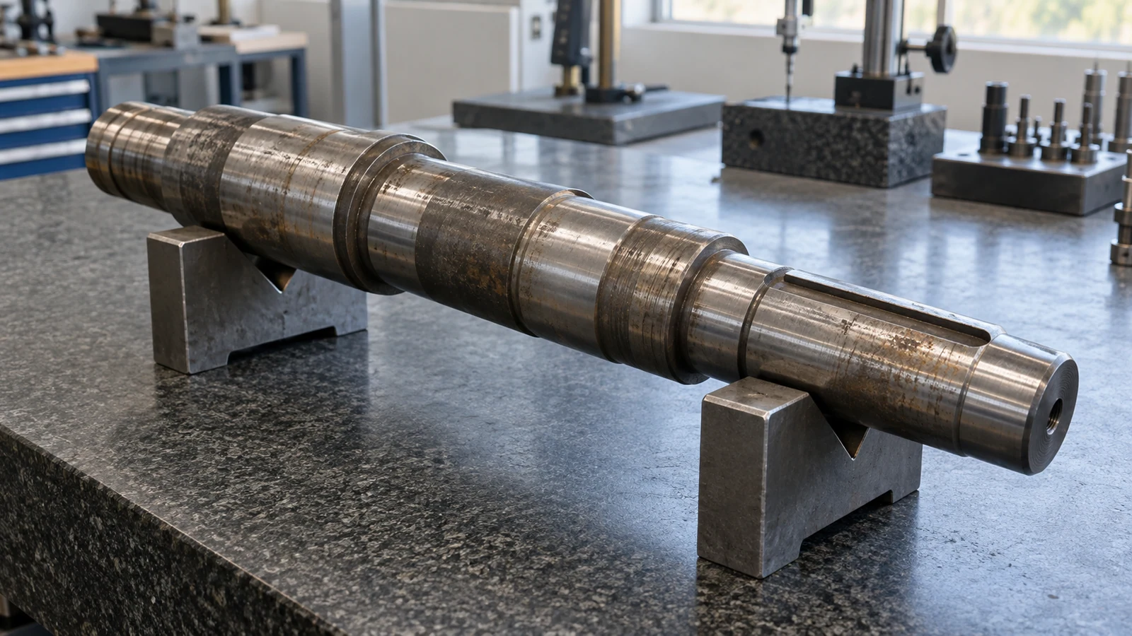
For a stepped pump shaft, record the relationship between bearing locations, seal location, impeller position, and coupling interface. A collection of diameters without a common datum scheme does not fully describe the shaft.
| Feature | Useful evidence beyond the worn sample |
|---|---|
| Bearing seat | Bearing identification, mating fit requirement, and an unworn reference if available |
| Seal location | Seal drawing, sleeve arrangement, working length, and surface requirement |
| Shoulder or spacer face | Assembly stack, axial location, and contact condition |
| Coupling interface | Hub bore, key or drive arrangement, and installation method |
| Hydraulic surface | Original performance information, mating clearances, and comparable unworn geometry |
Measure several positions where wear or distortion is possible. A single diameter can miss taper, ovality, or localized damage. Record the measurement method and uncertainty where the required tolerance approaches the capability of the method.
The mechanical seal identification guide can help resolve the seal interface when that part of the assembly is also uncertain. It does not replace the complete pump dimensional assessment.
Separate measured geometry from nominal dimensions
A practical reconstruction drawing distinguishes dimensions taken directly from reliable surfaces from dimensions established through fit analysis, assembly relationships, or other records. That makes unresolved features visible before manufacturing starts.
Consider a hypothetical bearing seat measured at several positions between 49.91 and 49.97 mm. Those readings describe the current part. They do not establish whether the original nominal diameter was 50 mm, which tolerance applied, or how much of the variation comes from wear and measurement conditions.
The replacement diameter must be derived from the bearing, application, and required fit. The measured range remains useful as evidence of the removed component’s condition. It should not be averaged into a new nominal dimension simply because an average is easy to calculate.
The same principle applies to axial dimensions. Worn thrust surfaces and damaged shoulders can alter an assembly stack. Recover the functional relationship from more than one source, then express the chosen geometry through datums and tolerances that a manufacturer can inspect.
Material identification needs a delivery condition
Chemical analysis can help identify an alloy family, but the finished component’s properties also depend on manufacturing route and condition. Heat treatment, hardness, surface treatment, and prior repairs can all matter to the replacement.
For a shaft, the specification may need a grade, heat-treatment condition, hardness range, and requirements at functional surfaces. For a casting, the scope may include the selected cast grade, casting quality requirements, machining allowance, and inspection of critical regions.
A material substitution can be useful when the original grade is unavailable or poorly suited to the service. Keep that change explicit. It may affect machining, weldability, distortion, corrosion behavior, or the interface with another material. A replacement proposal should show whether the geometry remains the same and what additional verification the substitution requires.
Only provide drawings, models, and samples that the buyer is authorized to use for the replacement work. Agree on ownership and permitted reuse of the resulting manufacturing data as part of the project scope.
Plan acceptance before the first part is made
Inspection becomes more useful when it follows the recovered function. For a rotating component, this may include the relevant diameters, runout, concentric relationships, axial locations, surface finish, and balance requirements. A pressure-containing component has a different acceptance scope.
List the first-part checks alongside the drawing, including which interfaces can be checked in the workshop and which require assembly. If a hydraulic geometry changes, the required performance demonstration belongs in the project plan; a dimensional match alone answers a narrower question.
The inspection document matrix can organize the resulting records. The document set should follow the component’s requirements rather than becoming a generic stack of certificates.
Split the order at the useful decision points
For an obsolete component with limited records, separate the initial engineering deliverable from the manufacturing release. The first stage establishes the model, drawing, material basis, and open interface questions. The next stage manufactures the accepted design and verifies the agreed features.
This structure gives the buyer a concrete point at which to assess the reconstructed dimensions and the proposed manufacturing route. It also avoids treating an early sample-based estimate as a fully defined production quotation.
Once the first replacement is accepted, retain the controlled drawing, inspection record, and assembly findings. Future orders can then use a repeatable specification instead of reopening the same reconstruction problem each time the pump needs a part.
Put the guide into practice
Related specification and RFQ pages
Frequently asked questions
Is a 3D scan enough to order a finished replacement?+
A scan captures accessible surface geometry at a stated resolution. The order also needs functional datums, tolerances, material and condition, surface requirements, and acceptance criteria. Internal or worn features may require additional measurement and engineering interpretation.
Can a sample-based quotation include a material upgrade?+
Yes, as a separately defined option. Identify the proposed grade, manufacturing condition, and any dimensional or performance consequences so that the material change can be evaluated independently of reproducing the original fit.
Continue researching