Translate liquid-cooling demand into pump requirements: heat load, coolant flow, facility and CDU boundaries, materials, controls, and maintenance access.
On this page
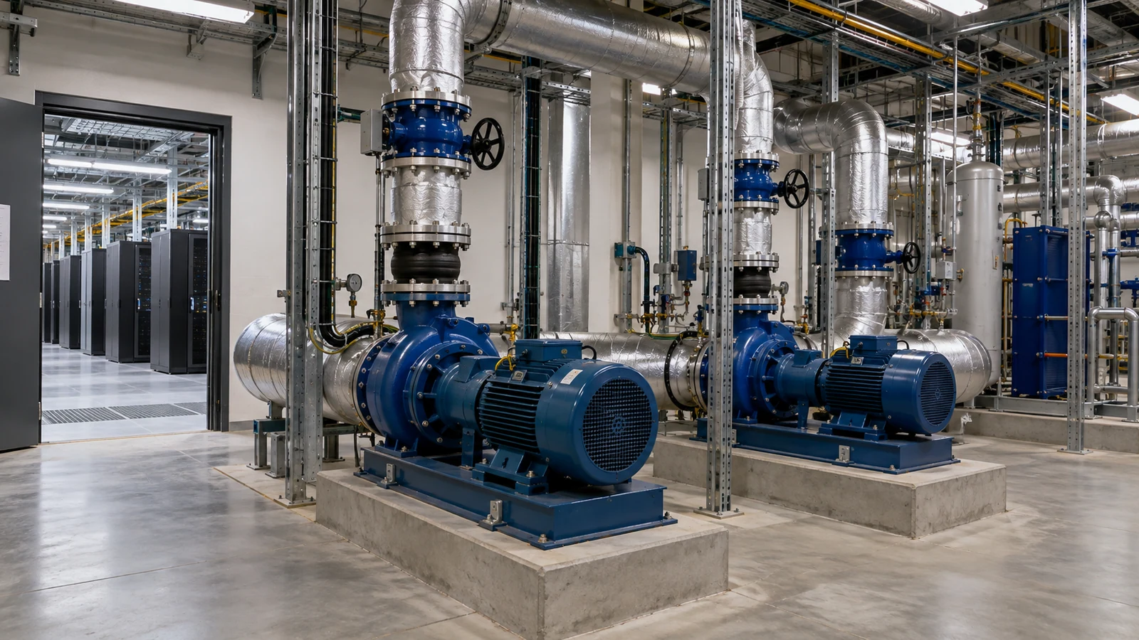
Growing computing demand is bringing more attention to the equipment that moves heat away from servers. For a component buyer, however, “data center cooling pump” is still too broad a specification. A facility-water pump and a compact pump inside a coolant distribution unit can have different fluids, hydraulic duties, controls, and maintenance constraints.
The first useful question is where the pump sits in the cooling architecture. That location determines which specifications matter and whether conventional mechanical sealing is part of the design at all.
Rising electricity use creates a sizing problem
The IEA’s April 2026 report, Key Questions on Energy and AI, examines the pressure that data-center growth places on energy infrastructure. Its accompanying analysis reports that data-center electricity consumption rose 17% in 2025, compared with 3% for electricity demand overall.
That trend explains the attention to cooling capacity, but it does not provide a pump duty point. Electrical demand becomes a procurement input only after the project defines the heat to be removed by each cooling system, its coolant temperatures, and the expected operating range.
A phased installation adds another dimension. Equipment sized for a fully populated hall may initially serve only a portion of that load. Minimum flow, speed control, and the performance of parallel pumps become relevant well before the final heat load is reached.
What separates the facility loop from the CDU loop?
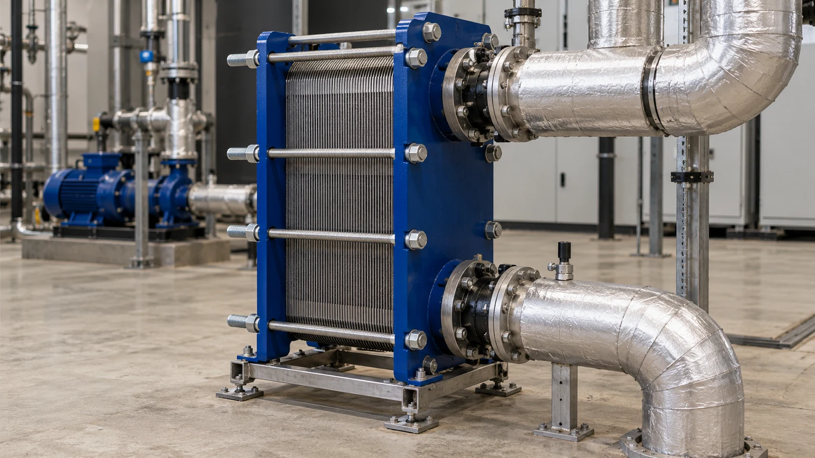
In a liquid-to-liquid coolant distribution unit, a heat exchanger transfers heat between the technology cooling circuit and the facility circuit. The fluids remain separate, allowing each circuit to have its own pressure, water-quality requirements, and materials. Other cooling architectures need their own boundary drawing.
| Part of the system | Typical selection focus |
|---|---|
| Facility distribution | Building pipe losses, available cooling source, seasonal conditions, and pump operating range |
| Liquid-to-liquid CDU | Heat-exchanger duty, internal pressure loss, control integration, and service access |
| Technology cooling circuit | Coolant chemistry, cold-plate and manifold requirements, cleanliness, and pressure limits |
| Rack branches | Flow distribution, connection losses, isolation, and leak detection |
Treat the CDU boundary as a physical interface. State which side supplies flow and pressure, which side controls temperature, and which measurements are available to the supervisory system. Otherwise, two vendors may each assume that the other provides a required control or pressure allowance.
The sealing architecture is equally specific. Moog’s CoreMotion liquid-cooling pumps, for example, integrate pump and motor elements in a design without rotating seals. That is a documented product approach, not a description of every data-center pump. A mechanical-seal specification belongs only where the selected pump design uses one.
Calculate coolant flow from the heat duty
For a single-phase liquid, the starting heat balance is:
Heat load = mass flow × specific heat capacity × temperature rise
Consider a simplified water example with 500 kW transferred to the liquid, an 8 K temperature rise, specific heat capacity of 4.18 kJ/(kg·K), and density of 1,000 kg/m³. Treat these properties as the assumptions for this calculation.
Mass flow = 500 ÷ (4.18 × 8) = 14.95 kg/s
Volume flow = 14.95 ÷ 1,000 × 3,600 ≈ 53.8 m³/h
At the same heat load and a 5 K temperature rise, the calculated volume flow becomes about 86.1 m³/h. A smaller permitted temperature rise therefore increases the required flow substantially. It also changes pipe and equipment losses, so it cannot be treated as a free increase in cooling margin.
These results size the heat-transport flow for the stated assumptions. They do not establish pump head. Head comes from the hydraulic model, including heat exchangers, cold plates, filters, valves, pipes, and the relevant system configuration. Use the actual coolant properties at operating temperature for the final selection.
Choose the operating range before the motor rating
A useful duty schedule includes initial occupancy, expected normal load, design load, and the operating condition after a planned pump is unavailable. For parallel pumps, the system curve and control strategy determine how the remaining machines share flow.
The evaluation should also include filter loading and changing valve positions. A pump that reaches the desired clean-system flow can behave differently when resistance increases or when only a few rack branches remain active.
For a closed circulating loop, total building height is not automatically an additional circulating head requirement. Static fill pressure, equipment pressure ratings, and the head needed to overcome circulation losses are separate design questions. Keeping them separate helps prevent an oversized pump from becoming the default answer to a tall building.
The resulting procurement document should include the required flow and differential pressure across the operating range, available inlet conditions, speed-control method, electrical supply, and the intended response to a pump or sensor fault. Motor power follows the selected pump and efficiency at those duties.
Materials and service access affect the component order
The coolant specification needs more detail than “water compatible.” Its treatment, additives, contamination limits, and contact with mixed materials affect the wetted component schedule. Cleanliness requirements can extend to manufacturing residues, assembly lubricants, and preservation before installation.
For custom piping or machined components, define wetted materials, surface condition, connection interfaces, pressure-test scope, and packaging cleanliness on the drawing. The build-to-print drawing guide is useful when turning an early cooling concept into a component RFQ.
Service access deserves space in the layout as well as in the specification. Isolation and drainage arrangements, connector access, and the physical path for removing a pump can determine how quickly a component is replaced. A compact installation that is difficult to service may be less attractive than a slightly larger arrangement with a clear maintenance path.
The procurement sequence is therefore heat load, circuit boundary, hydraulic range, fluid and material requirements, then component interfaces. That sequence connects a fast-growing market to equipment that can actually be specified and purchased.
Put the guide into practice
Related specification and RFQ pages
Frequently asked questions
Does every data center cooling pump use a mechanical seal?+
No. Pump construction varies by loop and equipment design. Some compact liquid-cooling pumps eliminate rotating shaft seals, while other installations use conventionally sealed pumps. Identify the installed architecture before specifying replacement sealing components.
Can a water duty point be used unchanged for a glycol mixture?+
Use properties for the actual mixture and temperature. Density and heat capacity change the flow needed for heat transport, while viscosity affects hydraulic losses and pump performance. The coolant supplier and pump curves provide the relevant inputs.
Continue researching